Chapter 2: Teaching 137 Volts to Behave ( High voltage safety design )
The morning we first connected up the full 137V pack I had a thought that I had been trying to avoid: we'd built something that could kill us, and now we had to teach it manners.
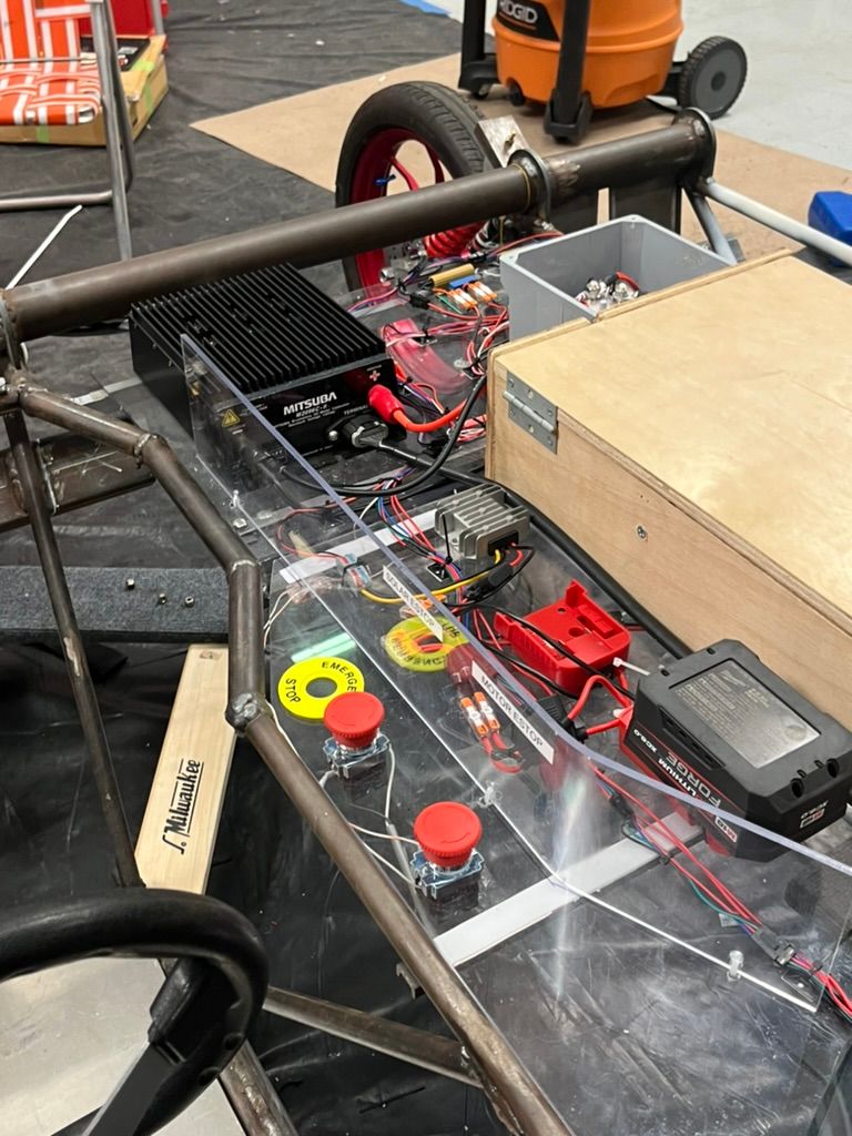
The Mitsuba motor controller sitting on our bench had 2000 microfarads of capacitance inside. Connecting them directly to our battery pack would create a huge inrush current and potentially damage the capicators. We needed what's called a precharge circuit, which could slowly charge the capacitors before closing the main contactors allowing for high power flow.
Designing the Precharge System
The precharge circuit serves a simple purpose: gradually charge the motor controller's capacitors through a current-limiting resistor before engaging the main contactors. This prevents the destructive inrush current that would otherwise occur. Our implementation uses a 500-ohm power resistor rated for 100W, which limits the initial current to approximately 270mA. The basic sequence follows these steps:
- Close the negative main contactor
- Close the precharge relay (connecting positive through the resistor)
- Monitor voltage equalization
- Close the positive main contactor
- Open the precharge relay
What distinguishes our system from simpler implementations is the active monitoring during step 3. Rather than using a fixed timer, we monitor the actual voltage rise via CAN bus messages from the motor controller.
Real-Time Voltage Monitoring and Fault Detection
The motor controller broadcasts its DC bus voltage every 100ms over CAN. Our drive computer uses this data to verify that precharge is proceeding normally. The expected voltage follows an RC charging curve:
V(t) = V_battery * (1 - e^(-t/RC))
With our 500-ohm resistor and 2000µF capacitance, the time constant is 1 second. We expect to reach 95% of battery voltage within 3 seconds. The monitoring system checks for several fault conditions:
Timeout: If voltage doesn't reach 95% within 10 seconds, we abort Slow rise ( or no rise) : suggests precharge circutry is not working Fast rise: Abnormally quick charging suggests disconnected components
During testing, we validated this system by introducing various faults: disconnected cables, additional capacitance, and partial shorts using power resistors. Each failure mode produced a distinct voltage signature that our monitoring system correctly identified.
Throttle Safety
One of our types of stories to hear and share revolve around solar car horror stories. There was one instance where a solar car would apply throttle whenever the 5v rail sagged, or the motor would never be at 0% and would require a controller reset.
A critical safety concern in any electric vehicle is uncommanded acceleration. In our system, a broken throttle wire could float to any voltage, potentially commanding full power unexpectedly. This is pretty bad.
Our throttle architecure goes as follows. Analog throttle pedal -> throttle subconputer -> (canbus) Drive computer -> throttle subcomputer -> motor controller.
The analog pedal takes the physical position and represents it as a 0-4.7V input. Then it broadcasts this every 10ms over the canbus. The Drive computer takes the raw position and scales it into a requested current setpoint, taking in consideration the max allowable current for that given moment in time as reported by the BMS. The BMS can de-rate the battery at any time, if temperature, internal resistance, or voltage parameters go out of range, this derate is gradual, but the drive computer must respect if otherwise a full contactor trip will occur. The throttle subcontroller takes this requested current and maps it to an analog output for the motor controller.
You may notice there are alot of steps in this chain for failure, and also uncommanded throttle outputs.
Layer 1: Redundant Monitoring
The drive computer monitors both the commanded throttle position and actual motor current reported by both the motor controller and BMS. Any discrepancy triggers our safety cascade, which usually involves a primary contactor opening.
Layer 2: Heartbeat Monitoring
Every (critical) control module must send a CAN heartbeat every 100ms. Three missed heartbeats trigger immediate safety action. This catches both communication failures and controller crashes. At the time of writing the only critical control modules are the instrumentation, and throttle subcontrollers. Lighting controllers will not cause a contactor trip but will raise alerts.
We validated this system through deliberate fault injection: disconnecting wires, inducing noise, and simulating controller failures. In every test, the system isolated the battery and high voltage within our 2-second safety window.
BMS Integration and Dynamic Derating
The Orion 2 BMS continuously monitors our battery pack and broadcasts operating limits over CAN:
Maximum discharge current Maximum charge current Maximum regenerative current State of charge Pack temperature Minimum cell voltage
Rather than allowing the BMS to directly cut power (which could be dangerous during operation), we implement dynamic derating. The drive computer adjusts throttle mapping based on BMS limits, ensuring we never exceed safe operating parameters. For example, if the BMS reports a maximum discharge current of 80A (due to temperature), the throttle map scales accordingly:
Normal operation (130A max):
Throttle 0%   -> 0A
Throttle 50%  -> 65A
Throttle 100% -> 130A

Derated operation (80A max):
Throttle 0%   -> 0A
Throttle 50%  -> 40A
Throttle 100% -> 80A
Communication Architecture
All safety-critical components communicate via CAN bus at 500kbps. We chose CAN for its inherent reliability features:
Differential signaling for noise immunity Built-in error detection and retransmission Message prioritization Multi-master capability
Our CAN message priority scheme ensures safety-critical messages take precedence:
BMS fault conditions (highest priority) Throttle commands Motor controller status Telemetry data (lowest priority)
Key Design Decisions
Several design choices proved particularly valuable:
- Active monitoring over fixed timing: Detecting actual system state rather than assuming normal operation caught several issues during testing that timer-based systems would have missed.
- Graduated responses over binary shutdowns: Allowing degraded operation kept the vehicle moving safely rather than creating potentially dangerous sudden power losses.
- Redundant monitoring paths: Having both motor controller and BMS report current provided cross-validation and caught a calibration error.
- Comprehensive telemetry: Real-time visibility into all parameters enabled rapid troubleshooting and validated our safety systems were functioning correctly.
Building safety-critical systems for a high-voltage vehicle taught us that paranoia in design leads to confidence in operation. Every additional check, every redundant monitor, every graduated response contributed to a system that could fail safely rather than catastrophically. The investment in sophisticated monitoring and control systems paid dividends in both safety and reliability throughout the competition.