Chapter 1: Building a 5kWh Battery Pack for Solar Car Racing: Lessons in High-Voltage Systems
Preface
This was my introduction to the unforgiving nature of high-voltage battery systems. Building a 5.25kWh pack for our high school's solar racing vehicle meant working with 429 lithium cells at 137 volts—enough energy to power a house for half a day, or if mishandled, create a very expensive and dangerous situation. The incident taught me that in high-stakes engineering, the difference between success and failure often comes down to systematic verification at every single step.
The Unscheduled Appearance of Magic Smoke
It's 11:47 PM on a Tuesday in November, and I'm watching 137 volts arc across a nickel tab that is beginning to turn liquid. The smell of ozone mixes with the distinct aroma of terror-induced sweat as I realize that our "perfectly safe" high-voltage system has just demonstrated why people probably don't let high schoolers build battery packs in their garage.
Aside from the now vaporized nickel strip, the highly flammable 18650s that sat just adjacent seemed to be unharmed. I looked over at my emergency bucket of sand.
The emergency bucket of sand—which I'd like the accident investigation board to note was present and within panic-reach, sat uselessly in the corner of the room.
How to Convince Yourself You're Qualified (Spoiler: You're Not)
About a month earlier, I am sitting in our school's library researching which 18650 battery we use in our solar vehicle. The plan was, to build a 5.25kWH battery pack to race in the 2025 solar car challenge. The reason needs to be as close as possible to 5.25kWH is that 1) the solar car challenge caps us at that capacity, and 2) the more energy we bring into the race in the form of stored electrical energy, the farther we will be able to go and drive. The race format has us driving for 4 days, 7.5 hours each day. At the core of the solar car is the battery, which is why we started with we designed it first.
Physics tells us that power equals voltage times current. To push 1500 watts, we could use 15 volts at 100 amps, or 150 volts at 10 amps. Same power, vastly different consequences. Resistive losses scale with the square of current (P = I²R), so 100 amps generates 100 times more waste heat than 10 amps through the same cables.
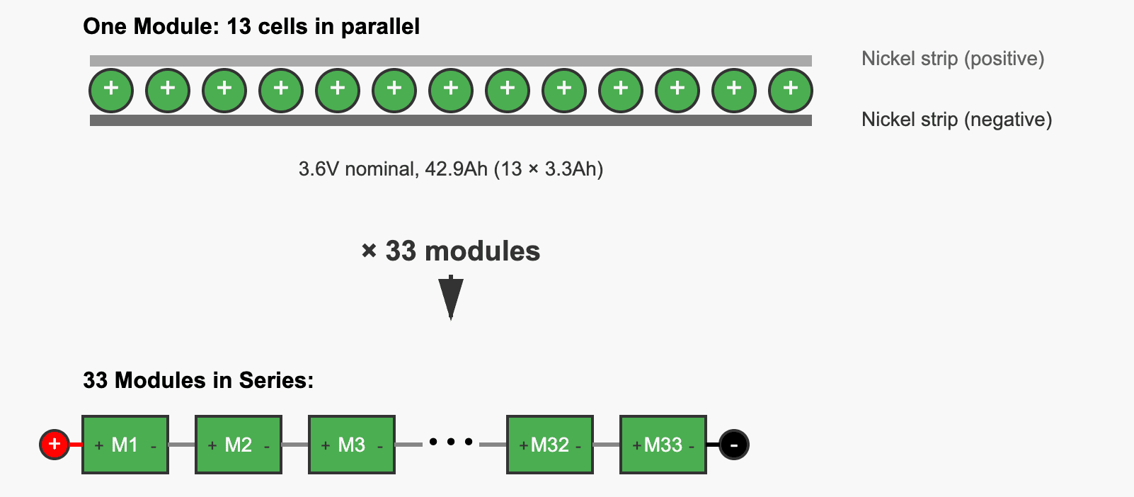
So we know we want to maximize voltage. The math worked backwards from our constraints. Competition rules capped us at 5.25 kWh total capacity. Our motor controller's 160V maximum set the voltage ceiling. Each Sanyo NCR18650GA cell delivered 11.88 watt-hours (3.3Ah × 3.6V nominal), giving us a budget of 441 cells maximum. We can arrange these 441 cells in whatever configuration we want but we cannot have more as that would put us over the 5.25kWH limit. For voltage, 33 cells in series hit 138.6V at full charge—safely under our controller's 160V limit while maximizing our voltage advantage. That left us with 13 parallel strings for redundancy and current capacity, totaling 429 cells and 5.09 kWh—just under the limit with margin for safety. That is how we got the 33s 13p configuration, a result of optimizing within boundaries.
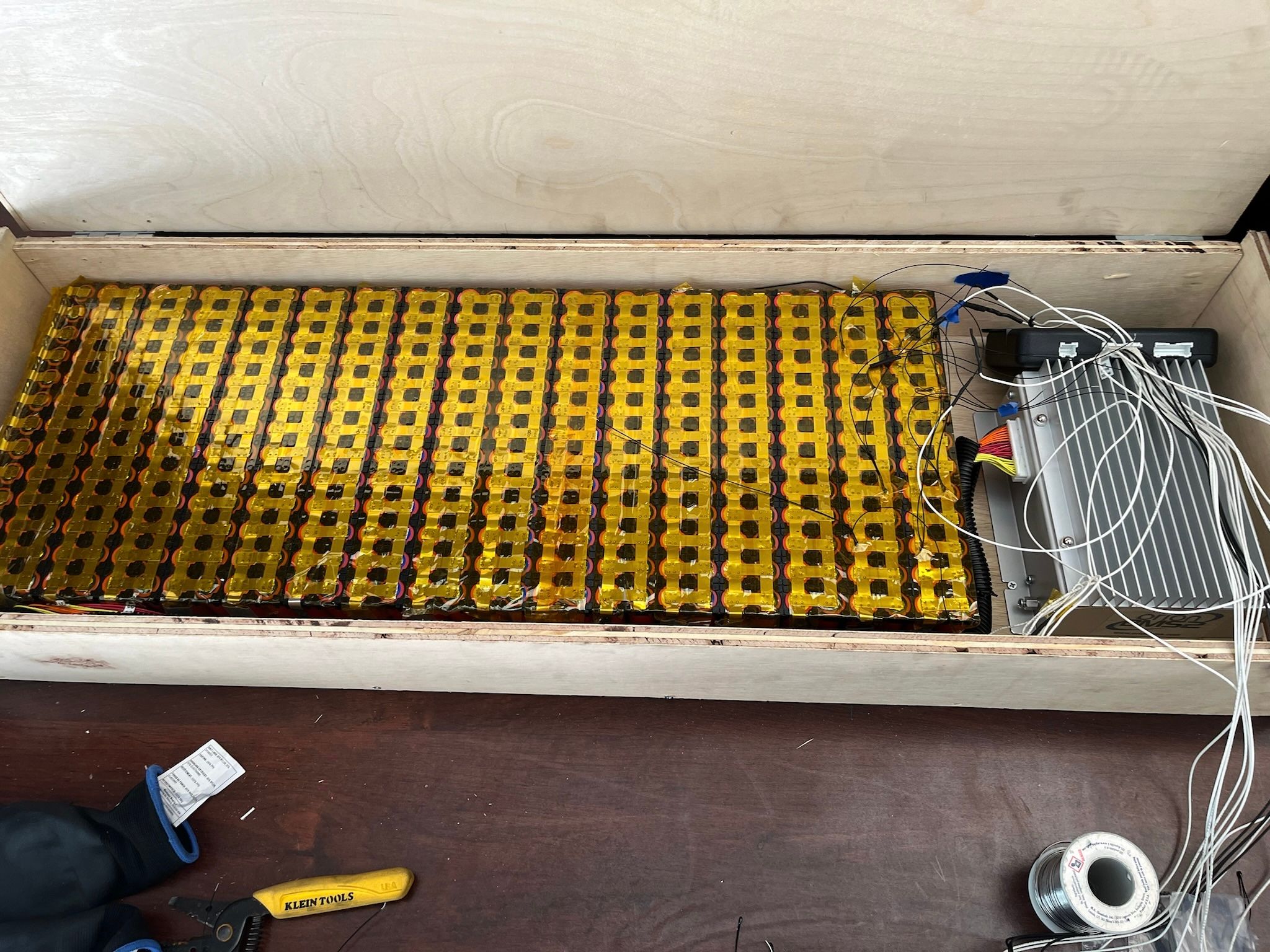
The assembly plan I sketched out one afternoon was simple. Take 13 cells, spot weld nickel strips across all their positive terminals, then another strip across the negatives—boom, one parallel module. Repeat 33 times. Connect positive to negative between modules with more nickel strips, creating a serpentine path of electrons from 0V to 137V. I even drew it up in CAD, each nickel strip perfectly aligned, every connection clean and geometric. The whole thing would take maybe a weekend, I figured.
Easy.
429 Precision Welds
The problem is that 18650 cells really, really don't like sustained heat. Apply a soldering iron's 350°C tip to a cell for more than a second, and you risk breaking down the internal separator, creating an internal short that turns your battery into a very expensive Roman candle. That's why spot welding is the only sane way to connect them. If a cell takes on too much heat and decides to take retaliate by venting with flames, it could cause a chain reaction setting the whole pack on fire.
Okay, so three steps to build this pack. Make a parallel module of 13 cells, repeat 33 times, make the series connections.
The parallel connections were deceptively straightforward. Cut a nickel strip long enough for 13 cells, spot weld across all the positive terminals. Flip the module over, repeat for the negatives. Yes, doing this 33 times was tedious, but it was just repetition. Muscle memory kicks in after module five or six. The real nightmare began with the series connections.
Here's where the geometry turns sadistic. To connect module 1's negative to module 2's positive, you need to bridge specific cells, but not just any cells. You need bridges between cells 1-2, 3-4, 5-6, and so on, creating a serpentine current path. To distrubute current evenly, you need to bridge 13 times per series connection. Bridge cells 1 and 3 instead of 1 and 2? Congratulations, you've just created a dead short across an entire 13-cell parallel group. Here's the thing: when you're staring at 429 cells arranged in a grid, exhausted from hours of welding, every cell starts to look identical.
The math of this completely hypothetical mistake is sobering. Each parallel group can deliver about 130 amps of short circuit current (13 cells × 10A each). That nickel strip you accidentally placed wrong? It turns into molten metal spraying across your other cells. The energy release is instant: about 500 joules dumped in milliseconds, enough to vaporize the nickel and potentially puncture adjacent cells.
And that's how my Tuesday night in November started, watching probably 15 hours of my handiwork potentially destroy my house. Because I'd counted wrong.
I love modular design!
Thankfully, I wasn't completely brainless in my approach. Instead of building all 33 modules and then attempting to series-connect them in one marathon session of potential disaster, I'd divided the pack into three sub-assemblies: three groups of 11 series modules The plan was to fully complete each sub-assembly, test it at a safer ~40V, and only then connect them together for the full 137V experience.
This decision, made only because our workbench literally couldn't fit 33 modules at once, saved me from having to rebuild the entire pack. The short had only affected the 13 cells in that one parallel section. Technically the other 10 modules in that sub-assembly were fine, but the shorted cells were soldered to the healthy ones before they were shorted and ripping them off was out of the question.
So I rebuilt all 11 modules. Two more days of cutting nickel strips, aligning cells, spot welding until my eyes crossed. This time I used a Sharpie to mark every single connection before welding, turning each module into a color-coded map of exactly where current should and absolutely should not flow.
Friday afternoon, 7 PM, the rebuilt sub-assembly tested perfect. 46.2V, exactly what 11 modules should produce. I connected it to the other two sub-assemblies with a multimeter checking continuity at every step. 137.4V appeared on the display. Success. Except it wasn't over. Not even close.
34 Chances to Destroy $2,000 - Wiring up the BMS
Remember earlier when I explained that soldering to 18650 cells was electrical suicide? Well, the Battery Management System (BMS) demanded we do exactly that. The Orion 2 BMS needed to monitor the voltage of every single series connection, which meant 34 wires (33 modules plus ground) that had to be attached to specific points in our pack.
The solution was nickel tabs. They were small strips that we'd spot weld to the cells first, then solder wires to the tabs. The tabs would act as thermal barriers, absorbing and dissipating heat before it could reach the cells. In theory, foolproof.
If the series connections were a minefield, the BMS wiring was 4-dimensional chess. With exploding pieces. And the board was on fire.
Each sensing wire had to connect to the exact junction between modules. Wire 0 to the negative terminal of module 1. Wire 1 to the positive of module 1 (which is also the negative of module 2). Wire 2 to the positive of module 2. And so on, 34 times.
Connect wire 15 where wire 16 should go, and the BMS sees module 15 as having double its actual voltage while module 16 appears to not exist. Best case scenario: the BMS refuses to initialize and throws an error code. Worst case: the BMS tries to "balance" this impossible voltage difference by dumping current through its balancing resistors, turning your $2,000 monitoring system into the world's most expensive space heater.
Learning From Earlier Mistakes
I labeled each wire three times—at the BMS connector, at the midpoint, and at the solder point. Then I had Max double-check my work. Then I physically traced each wire with my finger while reading the connection map out loud like some kind of electrical rosary. The phrase "measure twice, cut once" became "measure seventeen times, question your entire existence, measure again, then maybe solder." 5 painful hours later, we were finished with the BMS connection.
At this point, we stopped. Completely. No more welding, no more wiring, no more "just one more solder connection before dinner." We spent an entire weekend doing nothing but quality control.
Making it safe
Every single weld got the multimeter treatment. Every series connection was verified for continuity. Every parallel group was checked for internal resistance. The battery cells themselves were the nuclear core of our system: Maximum danger, no margin for error. Each layer outward from those cells needed to add protection, not just electrically but physically.
We attacked every exposed connection with heat shrink like we were weatherproofing for a hurricane. Each nickel tab that connected to the BMS got buried under kapton tape, the same stuff they use on rockets. Then heat shrink over that. It looked like a kindergartener's art project, but every piece of electrical insulation was one less opportunity for an accidental short.
The transformation was complete when we finally connected the BMS and gave it control of the main contactors. After that, no current could leave the battery pack and the outputs of the battery were cold ( no voltage) unless the BMS closes the main contactor. This made onboarding new team members and having people work close to the battery pack much safer as we could guarantee there was no power throughout the car.
Having the BMS in command with contactors instead of our haphazard "cover the outputs with electrical tape" felt like hiring a bodyguard for a celebrity we'd been personally protecting with a pool noodle.
The BMS now stood between our battery and the outside world, monitoring temperatures, voltages, and current flow with millisecond precision. If anything went wrong—overvoltage, undervoltage, overcurrent, overtemperature, or just bad vibes—it would cut the contactors. The battery was finally contained, monitored, and policed by multiple layers of both physical and electronic protection.
How we integrated this paranoid masterpiece with the rest of the solar car's systems—and discovered entirely new ways things could go wrong—is a story for part 2!